MIL-STD 810, Method 501 High Temperature Testing is used to evaluate the effects of high temperature conditions on performance, materials, and integrity. Method 501 is applicable for temperature testing products that are deployed in areas where temperatures (ambient or induced) are higher than standard ambient. Note, the latest revision of this method is 501.7 from MIL-STD-810H.
Method 501 is limited to evaluating the effects of relatively short-term (months, as opposed to years), even distributions of heat throughout the test item. This method is not typically practical for evaluating materials where solar radiation produces thermal gradients or photochemical effects. Method 505 is used to test the effects of solar radiation. It is also not practical to evaluate degradation that occurs from continuous long-term exposure to high temperatures where synergetic effects may be involved.
The following are typical failures that could occur from products used in high temperature environments.
- Parts bind from the differential expansion of dissimilar materials.
- Lubricants become less viscous; joints lose lubrication by the outward flow of lubricants.
- Materials change in dimension.
- Packing, gaskets, seals, bearings, and shafts become distorted, bind, and fail causing mechanical failures.
- Gaskets display permanent sets.
- Closure and sealing strips deteriorate.
- Fixed-resistance resistors change in values.
- Electronic circuit stability varies with differences in temperature gradients and differential expansion of dissimilar materials.
- Transformers and electromechanical components overheat.
- Operating/release margins of relays and magnetic or thermally activated devices alter.
- Shortened operating lifetimes.
- High pressures are created within sealed cases (batteries, etc.).
- Discoloration, cracking, or crazing of organic materials.
- Out-gassing of composite materials or coatings.
- Failure of adhesives.
MIL-STD-810 Method 501 Tests: High Temperature Procedures
- Procedure I – Storage. Procedure I is for testing products that are stored at high temperatures. After the high temperature storage test is completed, an operational test at ambient conditions is performed. Procedure I can be either a cyclic temperature test or a constant temperature test.
- Procedure II – Operation. Procedure II is used to investigate how high temperatures could affect the performance of items while they are operating. Temperature Procedure II can be performed as either a cyclic temperature test or a constant temperature test.
- Procedure III – Tactical-Standby to Operational. This temperature procedure evaluates the material’s performance at normal operating temperatures after being presoaked at high non-operational temperatures. An example of Procedure III is a product that is stored in an enclosed environment that develops high internal temperatures before being removed and then operated in a relatively short period of time.
What is the procedure for MIL-STD-810 High Temperature Testing?
First, identify the high temperature levels, test conditions, and applicable procedures. DES can help determine the appropriate temperature ramp rates and durations of the tests based on the equipment’s intended use and the operating environmental conditions. Consider the following climatic temperatures from Table 501.7-I. (MIL-STD-810H):
| Design Type | Location | Ambient Air oC (oF) | Induced2 oC (oF) |
|---|---|---|---|
| Basic Hot (A2) | Many parts of the world, extending outward from the hot dry category of southwestern United States, northwestern Mexico, central and western Australia, Saharan Africa, South America, Southern Spain, and southwest and south central Asia. | 30 – 43 (86 – 11) | 30 – 63 (86 – 145) |
| Hot Dry (A1) | Southwest and south central Asia, southwestern United States, Saharan Africa, central and western Australia, and northwestern Mexico. | 32 – 49 (90 – 120) | 33 – 71 (91 – 160) |
Next, determine whether a constant temperature test or a cyclic temperature test is appropriate. Constant temperature testing is used only for items situated near heat-producing equipment or when it is necessary to verify the operation of an item at a specified constant temperature. The duration for constant temperature test temperature is at least two hours following test specimen stabilization.
For cyclic exposure, there are two 24-hour cyclic profiles contained in Tables 501.7-II and 501.7-III. The number of cycles for the Procedure I storage test is a minimum of seven to coincide with the one percent frequency of occurrence of the hours of extreme temperatures during the most severe month in an average year at the most severe location. The minimum number of cycles for the Procedure II operational testing is three. This number is normally sufficient for the test item to reach its maximum response temperature.
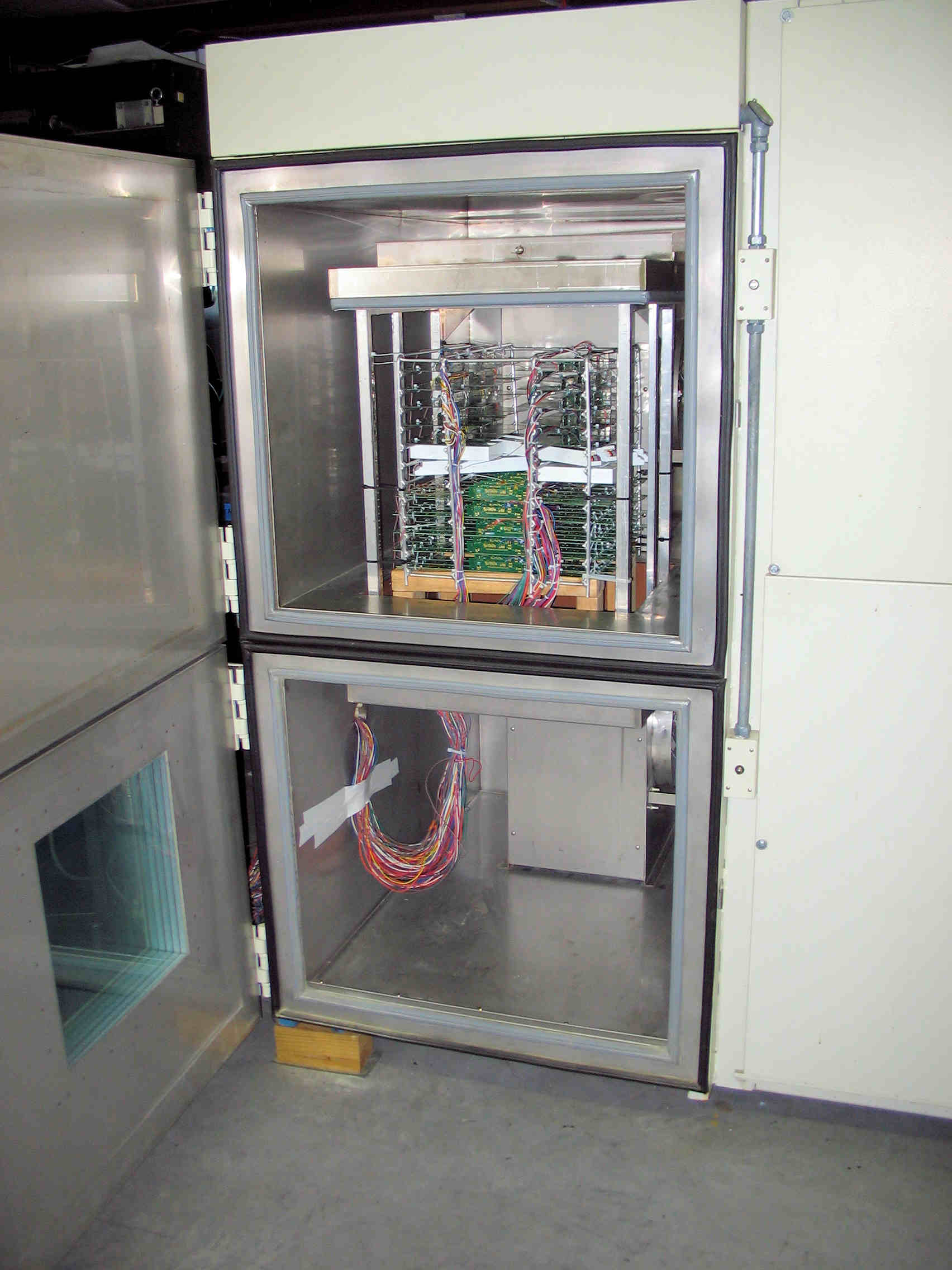
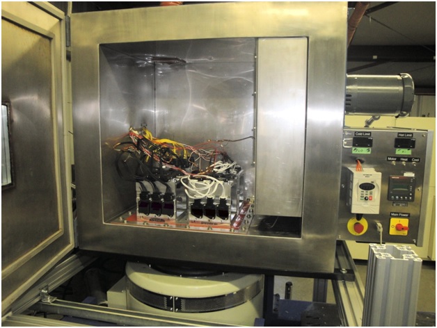
You can trust the DES MIL-STD-810 High Temperature Testing lab
Advantages with DES :
- DES is A2LA accredited to MIL-STD-810, Method 501 High Temperature Testing
- DES has extensive experience running MIL-STD-810 Method 501.7 high temperature Tests
- DES has multiple temperature chambers capable of performing MIL-STD-810 high temperature compliance testing
Contact us today to to discuss testing your product in our MIL-STD-810 accredited Test Laboratory.