This is another part of a series of blog posts concerning the MIL-STD 810 Shock Section, Method 516. This blog was written with reference to MIL-STD-810G w/Change 1 dated 15 April 2014. DES has the experience and expertise to run your MIL-STD-810 test. For more information, please check out our DES shock testing services page and our other MIL-STD-810 shock testing blog articles:
MIL-STD 810, Method 516, Shock Testing Overview
MIL-STD 810, Method 516, Shock Testing Procedure I – Functional Shock
MIL-STD 810, Method 516, Shock Testing Procedure II – Transportation Shock
MIL-STD 810, Method 516, Shock Testing Procedure III – Fragility
MIL-STD 810, Method 516, Shock Testing Procedure IV – Transit Drop
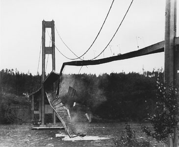
Crash hazard shocks apply to materiel mounted in air or ground vehicles. Shock testing according to Procedure V of MIL-STD 810, Method 516 is intended to test the strength of products during a crash situation to verify that parts do not break apart, eject and become a safety hazard. Failures of this nature could cause dangerous projectiles that could impact occupants or create significant damage to the vehicle.
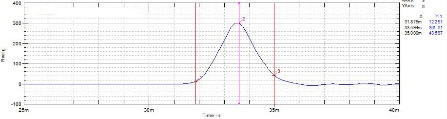
This article will focus on the shock test condition when measured field data is not available and the testing will use classical shock impulses. The terminal peak sawtooth is the default classical shock pulse to be used for this condition. Figure 516.7-10 from MIL-STD-810 shows its shape and tolerance limits. Table 516.7-IV contains the terminal peak sawtooth default test parameters for Procedure V – Crash Hazard Shock. In limited cases a half sine shock impulse is specified. Its shape and tolerance limits are shown in Figure 516.7-12.
Continue reading MIL-STD 810, Method 516, Shock Testing Procedure V – Crash Hazard Shock →